and high-voltage electric equipment
10 Chelyabinskaya Str., Ozersk, Chelyabinsk region, 456783, Russia
Phone: (35130) 4-36-40; fax: (35130) 4-87-15; e-mail: enerprom@aopoes.ru
Sales department. Phone: (35130) 4-82-45, 4-17-79; fax: (35130) 4-46-83; e-mail: marketing@aopoes.ru


 Non-standard electric equipment up to
  Standard electric equipment up to 1000 V
 Electric equipment above 1000 V
Complete distribution devices KRU-APS(E) of the voltage 6 and 10 kV
Complete transformer substations of KTPK-E type with the capacity from 25 up to 630 kVА and voltage up to 10 kV
Front side access switchgears of KSO-203 series
Complete switchgears of K-01E series
Complete switchgears of K-01ES series
Indoor transformer substations of KTPV series of capacity from 250 up to 1000 kVА and voltage up to 10 kV
The station of commercial account of 10 (6) kV (SCA)
 Electrochemical protection
 Block-module constructions
 Metal working and services
|
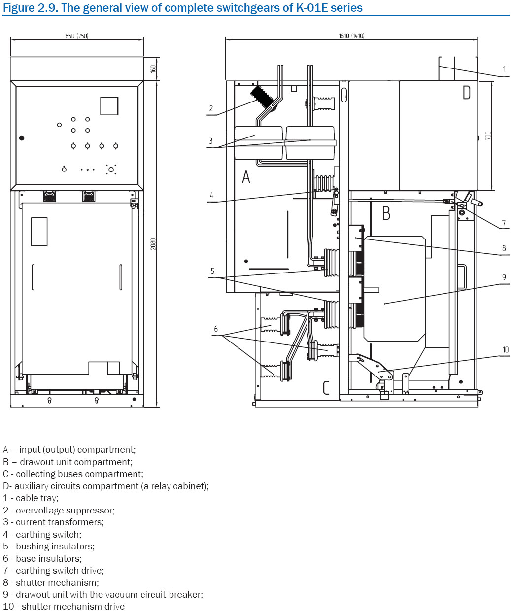
Complete switchgears of K-01E series
Switchgears of K-01E series are applied as complete switchgears of 6-10 kV, including switchgears of transformer substations for electric networks of industry, agriculture, power plants and railway transportation electrification. The device meets the requirements of Technical Conditions 3414-042-32574607-2004. The certificate of conformity № РОСС RU.ME25. B01203.
The example of symbolic notation of the switchgear with the main circuit diagram №11, with overvoltage suppressors, with vacuum circuit-breaker VBM-10-20/1000 with electromagnetic drive, with arrangement of phases of buses at front elevation АВС, rated current 630 A, thermal current 20 kА, climatic modification UHL, category of installation 3.1: K-01E-11А 1-630/20 UHL3.1 The example of symbolic notation of switchgear with the main circuit diagram №01, with overvoltage suppressors, with vacuum circuit-breaker VD4 with electromagnetic drive, with arrangement of phases of buses at front elevation АВС, rated current 2500 A, thermal current 31,5 kА, climatic modification UHL, category of installation 3.1: K-01E-01А 5-2500/31, 5 UHL3.1 Operation conditionsК-01E switchgear panels are intended for indoor operation (climatic modification UHL3.1 in accordance with GOST 15150-69) under the following conditions:
Design and actionSwitchgear panels, depending on the diagram of the main and auxiliary circuits, have different functions:
К-01E switchgear panels provide convenience of examination, repair and dismantling of primary components during operation without voltage removal of collecting buses and the adjacent connections. K-01E panels of all modification types represent metal housing, welded of the bent sections. Apparatus and devices according to the main and auxiliary circuit diagrams are installed inside. K-01E panel consists of three basic parts: housing, drawout unit and relay cabinet. The panel is divided by walls and closing shutters into three compartments: high-voltage, cable incoming and collecting buses. Drawout unit represents a welded structure on which the high-voltage devices, according to the main circuit diagram, and contact system are installed. The complete K-01E switchgears are delivered as separate metal cabinets with elements for joining them. At the request of the customer switchgears are delivered by transport blocks of up to three cabinets in the block with the connections of the main and auxiliary circuits mounted within the block. The complete K-01E switchgears are designed for front and rear side access. In order to prevent erroneous operations there are the following interlocks in the panels:
Note - For realization of other kinds of interlocks (operative, safety, etc.) it is possible to install safety locks. In K-01E switchgears there is high-speed arc protection made with the use of overpressure unloading valves in combination with sensitive relays of arc protection of PD-02 or OVOD-M types. The control of overpressure unloading valves position is done with limit switches. Circuits of secondary switching of K-01E panel are placed in the relay cabinet. The relay cabinet represents a welded metal strucure. Low-voltage components of auxiliary circuits are mounted either on the rear wall, or on the rotary panel inside the relay cabinet. Secondary circuits diagrams are realized through a range of typical schemes using electromechanical relays, and also with the use of microprocessor relay protection devices of various manufacturers (of "Temp", "SEPAM", BMRZ, "Sirius" series and others). Safe work in a drawout unit compartment is provided by protective shutters which are automatically closed when the drawout unit is moved out from service position to testing position, thus blocking access to fixed contacts under voltage. In the closed position it is possible to lock the shutters in the lower part of the compartment. On the unit frame there are brackets, which operate the shutter mechanism, when the unit is moved in or out. Busbar bridges are a metal structure, collected of two frames with isolators, buses and busbar carriers installed on them (ЭПСЗ.685515.001-Ш, ЭПС3.685515.001-ШР). If the passage width in the switchgear is 4200 mm, an insert frame is installed between the frames. Busbar bridges are produced without disconnectors. Drives of these disconnectors are placed on the planes 200 mm wide, fixed between two end panels in the switchgears row (on the right or on the left). Features
   |

|


skilled consultants will help you to find optimal
decision for your business!
Phone: (35130) 4-36-40; fax: (35130) 4-87-15,
e-mail: enerprom@aopoes.ru, site: www.energoprom.biz, www.enprom.ru.